2014年4月6日 星期日

CC2530 Zigbee Module Development (1) - Source Code Not Release

CC2530 Zigbee Module Development (1) 

Network Topologic


Default Network Setting
Channel:0x26 、 PAN ID:Random

USART0 Setting
RX:P0_2 、 TX:P0_3
baud rate:57600 bps ( No flow control )

USART1 Setting ( For Zigbee Sensor Monitor )
RX:P1_7 、 TX:P1_6


Zigbee Sensor Monitor

Comparison with Packet Sniffer Tools


2014年4月2日 星期三

CC2530 8051 Integration Testing

CC2530 8051 Integration Testing

I/O Pin Define


Circuit Diagram
AT24C64 Device Address - 0xA6


USART Command Basic Format


SOP:0xFE
LEN:DATA LENGTH
FCS:CMD xor LEN xor DATA

Error Handler
ERR_MODE_FAIL return 0x00
ERR_MODE_SUCCESS  return 0x01
ERR_MODE_CHECKSUM_ERR  return 0xFF

LED CMD - 0x00B0


LED All ON : FE00B00100B1
LED All OFF : FE00B00111A0
BLED ON(RLED OFF) : FE00B00101B0
RLED ON(BLED OFF) : FE00B00110A1


IIC Byte Write CMD - 0x00B1

IIC Byte Write : FE00B10300077FCA
Write data to AT24C64,EEPROM Address = 0x0007,Write data = 0x7F


IIC Byte Read CMD - 0x00B2


IIC Byte Read : FE00B2020007B7
Read data from AT24C64,EEPROM Address = 0x0007


IIC Page Write / Multi Write CMD - 0x00B3 


IIC Page Write 
FE00B3230020208888888899999999AAAAAAAABBBBBBBBCCCCCCCCDDDDDDDDEEEEEEEEFFFFFFFF90

Write data to AT24C64,EEPROM Address = 0x0020,Data Length = 32 byte,Write data = 8888888899999999AAAAAAAABBBBBBBBCCCCCCCCDDDDDDDDEEEEEEEEFFFFFFFF


IIC Page Read / Multi Read CMD - 0x00B4 


IIC Page Read : FE00B403002020B7


PWM-1(Timer1-CH3) CMD - 0x00B5


MAX : FE00B50100B4
MIN : FE00B50101B5
HALF : FE00B50110A4
OFF : FE00B50111A5

MAX → MIN → HALF → OFF

PWM-2(Timer3-CH1) CMD - 0x00B6


MAX : FE00B60100B7
MIN : FE00B60101B6
HALF : FE00B60110A7
OFF : FE00B60111A6

MAX → MIN → HALF → OFF
KEY-1、KEY-3:Adjust PWM-2

AT93C46 SPI Byte Write CMD - 0x00B9


AT93C46 SPI Byte Write : FE00B9020011AA
Write data to AT93C46,Write Address = 0x00,Write data = 0x11


AT93C46 SPI Byte Read CMD - 0x00BA


AT93C46 SPI Byte Read : FE00BA0100BB
Read data from AT93C46 ,Read Address = 0x00


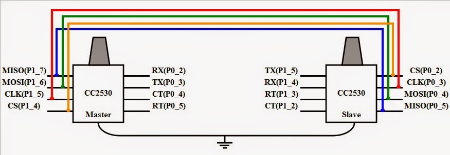
CC2530 8051 SPI Master and Slave data transceiver

CC2530 8051 SPI Master and Slave data transceiver

Circuit Diagram


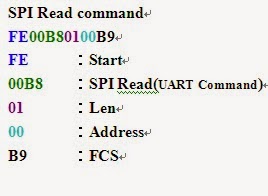
USART Command Format Define


CC2530 Slave Device Default Data


SPI Write / Read Command Format Define


Get Data 0xAA to generated clock for SPI slave device return data

Error Handler
SUCCESS return 0x01
FAIL return 0x00
CHECKSUM ERR return 0xFF

1. USART SPI Read Command - Read SPI slave device default data


2. USART SPI Write Command - Write data to SPI slave device 


3. USART SPI Read Command - Confirm the write data


CC2530 8051 Power Modes (PM2-Wake Up form the external interrupt or Sleep Timer)

CC2530 8051 Power Modes (PM2-Wake Up form the external interrupt or Sleep Timer) 

KEY Define
KEY1 Wake Up
KEY3 Go to PM2

Initialization State
B-LED OFF,R-LED Blinking

1. Press the KEY3 to go PM2,R-LED blinking stop
2. Press the KEY1 to wake up from PM2,RLED blinking
3. Press the KEY3 to go PM2,R-LED blinking stop
4. Don't Press the KEY1 to wake up,it will wake up from Sleep Timer after 10 seconds and  B-LED status will change


CC2530 8051 Power Modes (PM3-Wake Up form the external interrupt )

CC2530 8051 Power Modes (PM3-Wake Up form the external interrupt )

KEY Define 
KEY1(P0_1) : Wake Up 
KEY3(P1_2) : Go to PM3

Initialization State 
BLED,RLED Blinking

1. Press the KEY3 to go to PM3 and B-LED,R-LED blinking stop 
2. Press the KEY1 to wake up from PM3 and B-LED,R-LED blinking


CC2530 8051 I/O Interrupt (External Interrupt)

CC2530 8051 I/O Interrupt (External Interrupt)

Pin Define
P1_2 = KEY3

1. Press the KEY3 to trigger external interrupt and execute the interrupt function (R-LED Flash,B-LED OFF)
2. Release the KEY3(R-LED OFF,B-LED ON)


CC2530 8051 WDT(Watch Dog Timer)

CC2530 8051 WDT(Watch Dog Timer)

Pin Define

P1_2 = Output I/O Pin
P1_3 = Output I/O Pin

1. WDT Timer = 1 SEC
2. P1_2 initial value HIGH
3. Enter to MAIN function, P1_2 will change to LOW and P1_3 = !P1_3


WDT(Watch Dog Timer) NOT START


WDT(Watch Dog Timer) START